Discrete Components


How do Discrete Components Reduce Schematic Errors?
1: What are Discrete Components?
Discrete Components are an innovative feature of Integrated-system Design to help manage 'parts' within a component.
Here is a schematic drawing of a Promux Relay Module which features 4 SPDT Relay contacts controlled by Modbus RTU.
Often it is convenient to draw the component in this style.
Wires can be connected to relay contacts, RS-485 communications bus and 12-24VDC power supply etc.
But often it is also convenient to draw the component with the relay contacts separate from the power supply and RS-485 communication bus.
This can be accomplished using the 'Discrete Parts' feature of Integrated-system Design.
When designing the component, create one relay contact output and use the 'Create Discrete Group' feature to make 4 replications of the contacts.
The Schematic designer will then be able to 'extract' relay outputs, but most importantly, will only be able to extract 4 outputs which avoids the mistake of drawing more outputs than the component physically supports.
2: How do Discrete Components Reduce Schematic Errors?
This feature of Integrated-system Design came about from reading a schematic diagram from a 3rd party design company. The project required 5 relay contacts to control higher voltage relays.
The schematic contained a Promux PM4RO unit, but had 5 relay contacts associated with it. The PM4RO only has 4 contacts.
The Discrete Component feature manages 'sub' parts and prevents easily made mistakes such as this.
The project designer will only be able to 'extract' as many contacts as the component has.
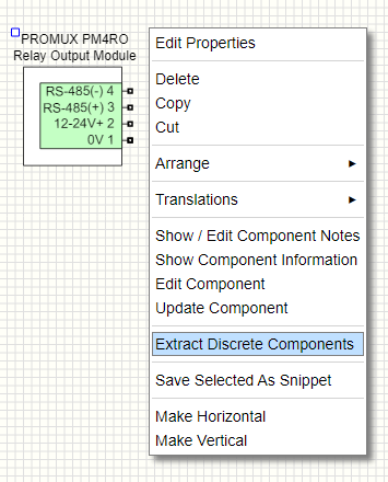
Extracting the 'sub / discrete' parts is done by right-clicking the component and selecting 'Extract Discrete Components'
Context menu to access 'Extract Discrete' dialog.
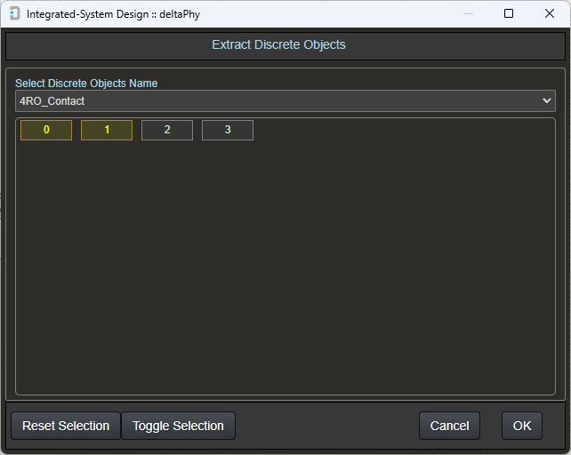
Use the drop-down menu 'Select Discrete Objects Name' in the Extract Discrete Objects dialog, to select the required discrete object group in the component.
Select which discrete parts you need in the schematic by clicking the '0', '1', '2', or '3' buttons.
If the component had 16 discrete parts in the selected group, then there would be 16 selection buttons etc.
Parts that have already been selected and placed in the schematic will be greyed out.
'Extract Discrete Component' Dialog.
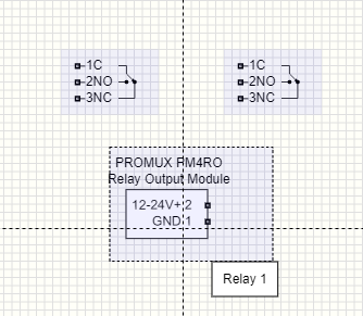
In this example, 2 of the 4 relay outputs have been extracted.
Hovering on a discrete component or an extracted part will highlight all parts belonging to that component.
This makes it easier to see which discrete part belongs to which component.
Image showing discrete component being hovered on.
This discrete component example shows the same Promus PR4O relay output with relays as discrete parts and also the RS-485 port as a discrete part.
It may be convenient to draw the port away from the main component.
In this example, the main component only has power supply inputs and all other parts are drawn separately and can be moved away from the component in the schematic.
Note that the RS-485 reference (GND) connection is connected to the power supply GND connection.
This is done using 'Interconnects' and is a feature used to connect parts of a component internally.
Click here for more information on InterconnectsImage showing RS-485 reference being hovered on.
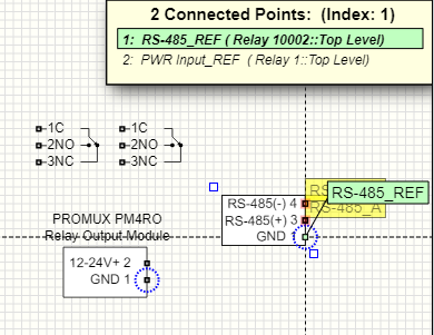
The RS-485 reference connection is being hovered on.
Note that there is an electrical connection between this reference and the power supply GND connection.
This is indicated by the flashing dotted blue circles and the overlapping points display.
The overlapping points display indicates the electrical objects that are connected to the hovered-on connection.