Integrated-system Design
Electrical schematic and layout software tool for
Integration, Automation and Control-system Design.
Example Component Models
Moxa Ethernet Switch
This image is in Footprint View in the Component Library Editor with the schematic indicator at the bottom right of the image. This indicator helps to match electrical objects in the footprint view with the same objects in the schematic symbol view.
Hovering on an electrical object in the footprint will highlight it in the schematic indicator. Hovering on an electrical object in the schematic indicator will highlight it in the footprint view.

Netcom Modem
This image is in Footprint View in the Component Library Editor with the schematic indicator at the bottom right of the image. This indicator helps to match electrical objects in the footprint view with the same objects in the schematic symbol view.
Hovering on an electrical object in the footprint will highlight it in the schematic indicator. Hovering on an electrical object in the schematic indicator will highlight it in the footprint view.

Campbell CR-310
This screenshot is a Campbell CR-310 shown in the Layout Editor.
This example shows one of the CR-310 SDI-12 ports being hovered on and the resulting heads-up display indicating the available protocols.
The Schematic Indicator (Bottom right) shows the Schematic Symbol. You can have unlimited versions of component symbols to suit your style of electrical drawing.
The communication protocols SDI-12 Master and Slave are displayed in the heads up display (top left corner), while the other 'stacked' objects (Voltage Output, Contact Closure and Digital Input) are displayed in the Overlapping Points display in the top right corner.

JACE-8000 BMS Controller
This screenshot is a JACE-8000 BMS Controller shown in the Layout Editor of the Component Library Editor.
This example shows one of the RJ45 Ethernet ports being hovered on and the resulting heads-up display indicating the available protocols.
The protocol Ethernet/IP is displayed in the heads up display (top left corner) which also indicates the JACE-8000 has a HTTP Server and is incompatible with PoE.

Other Component Examples
NEMA Symbols

IEC Symbols

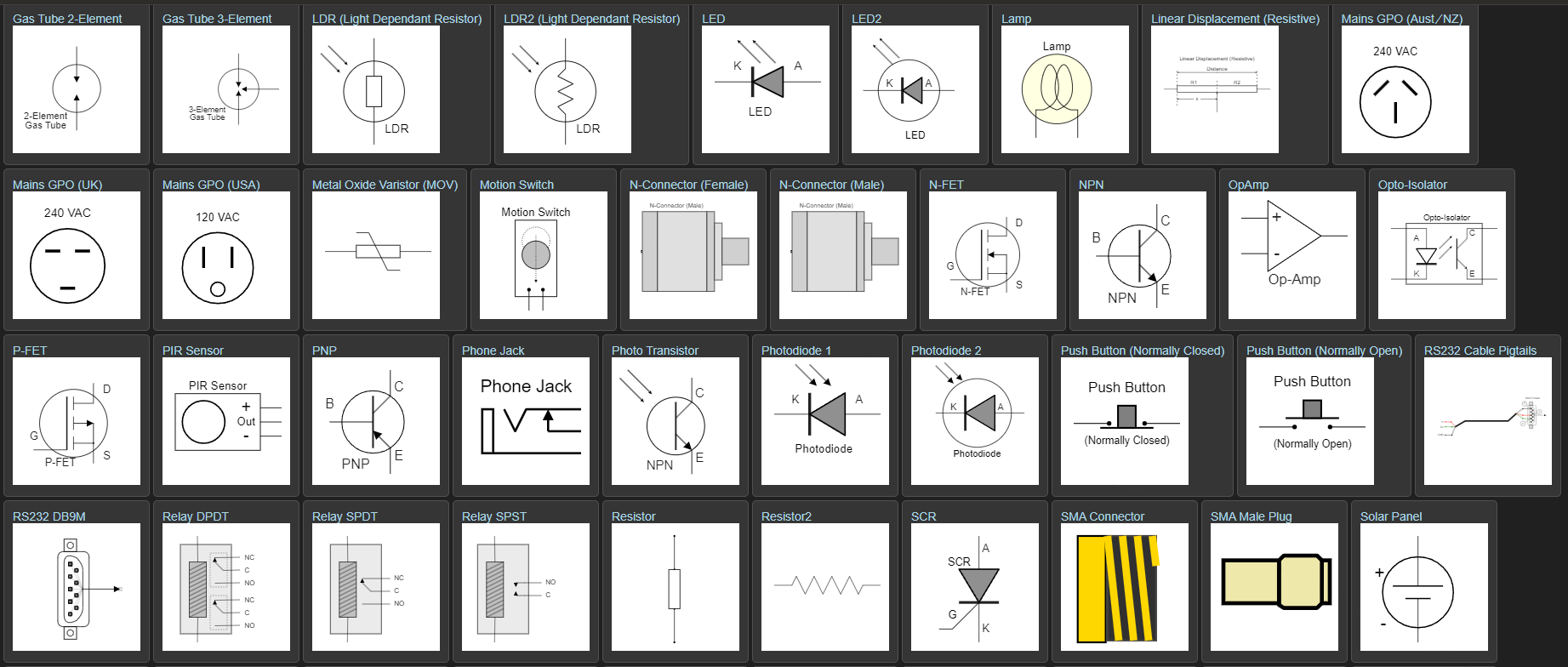
Electronic Symbols